Guide
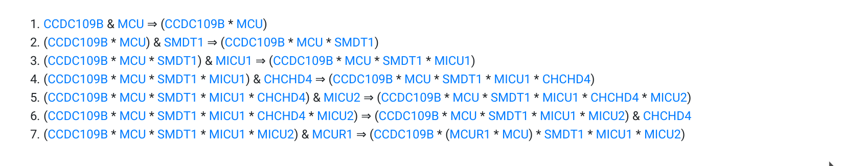
To explain how to read the logical information provided by MitopatHs, we illustrate the case of the Uniporter pathway. The biological steps leading to the formation of the Uniplex complex are represented as the following steps which are the logical representation (in Zsyntax language) of the biochemical reactions really occurring:
- & denotes the juxtaposition of two resources (i.e. molecules);
- * denotes the binding of two resources to form a complex;
- (), i.e. the parenthesis, are used to define complexes that contain sub-complexes, as Uniplex sub-complex (MCUR1 * MCU);
- ⇒ denotes a biological step
The steps above can be read as follows:
- given a protein CCDC109B and (&) a protein MCU, they react (⇒) producing the complex (CCDC109B * MCU); the bond between the 2 proteins of the complex is represented by *;
- given the complex (CCDC109B * MCU) and (&) a protein SMDT1, they react (⇒) producing the complex (CCDC109B * MCU * SMDT1); each bond between the 3 proteins of the complex is represented by *;
- the previous complex and (&) MICU1 react (⇒) producing the complex (CCDC109B * MCU * SMDT1 * MICU1); each bond between the 4 proteins of the complex is represented by *;
- the previous complex and (&) CHCHD4 react (⇒) producing the complex (CCDC109B * MCU * SMDT1 * MICU1 * CHCHD4); each bond between the 5 proteins of the complex is represented by *;
- the previous complex and (&) MICU2 react (⇒) producing the complex (CCDC109B * MCU * SMDT1 * MICU1 * MICU2 * CHCHD4); each bond between the 6 proteins of the complex is represented by *;
- CHCHD4 separates from the previous complex (⇒) producing the complex (CCDC109B * MCU * SMDT1 * MICU1 * MICU2) together with (&) a residual protein CHCHD4;
- the previous complex and (&) MCUR1 react (⇒) producing the complex (CCDC109B * (MCUR1 * MCU) * SMDT1 * MICU1 * MICU2), which corresponds to Uniplex, each bond between the 6 proteins of the complex is represented by *, the brackets allow to represent what is bond with what.
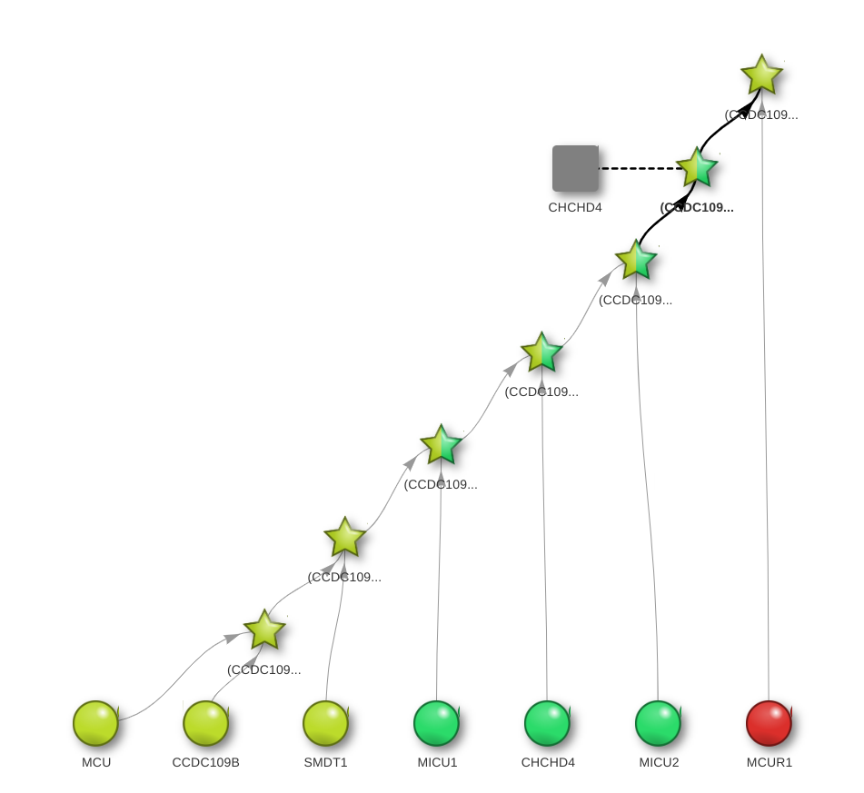
The graph-based visualization (the Dynamic View) of these steps interactively illustrates the pathway leading to the formation of Uniplex:
In this dynamic view,
- the circle denotes a protein in the initial aggregate,
- the star denotes an intermediate or final complex,
- the square denotes a residual protein.
The graph-based visualization illustrates which proteins in the initial aggregate bind to form an intermediate complex. In this view, the circle denotes a simple protein, the star denotes an intermediate or final complex, and the square denotes a residual protein. Colours denote the position of proteins and complex into the mitochondrion: red for the matrix, yellow for the internal membrane, green for the inter-membrane space, blue for the outer membrane and violet for the peri-mitochondrial space. The grey colour is reserved for unknown or irrelevant positions, while a star with multiple colours indicates a protein complex of proteins that occupy different sub-mitochondrial districts. For instance, the uppermost star in the figure corresponds to the complex produced by the 7th step (its full Zsyntax name appears when pointing the mouse over the star, and simple graph rearrangements can be done through mouse dragging). The two edges entering that star show that this complex is the result of the interaction between the aggregate obtained in the previous step and the MCUR1 protein, residing on the mitochondrial matrix.
All the steps of the Uniporter pathway can be summarized by the following biological theorem (see [1,2,3] for details):
MCU & CCDC109B & SMDT1 & MICU1 & CHCHD4 & MICU2 & MICUR1 => (CCDC109B * (MCUR1 * MCU) * SMDT * MICU1 * MICU2)NOTE: whenever multiple occurrences of the same resource are needed in a pathway, the premise of the corresponding theorem must explicitly list all the copies. e.g. the theorem P1 & P1 & P2 => P3 states that two copies of the protein P1 together with a single copy of protein P2 produce a single copy of the protein P3, as in this example (ComplexIII2 Assembly).
The same process has also a different visualization (Dynamic Mito-Location) which, step by step, focuses the location of the molecules at stake in the proper mitochondrion compartments. For example, always considering Uniporter pathway, we have (from the initial Step 0 to the final Step 6):


